 Czech
Czech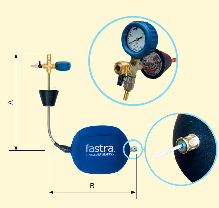
Type UBF-N-K
This is a version that includes an opening for the monitoring of the media pressure in a section of the closed pipeline upstream the closing balloon or in the closed section of the pipeline (if several balloon are used). Working part – for properties and description following the sheet 2.2 –3. Loading part – a fixed loading tube with a sealing plug, an opening/passage in the working part and loading tube ended with a self-closing quick acting coupling system, integrated pressure gauge, filling ball valve with a hose extension diameter 10 mm, identification plate. This type of the closing balloon in this versions is made of materials that must not be exposed to any organic solvents, oil products, fats, acids, caustics and their vapours. The version made be modified based on customer requirements (following the sheet 2.2-1).
| FOR STEEL PIPELINES | ||||||||
| Name | For pipeline DN/ID [mm] |
A [mm] |
B [mm] |
P1 [bar] |
P2 [bar] |
D [mm] |
H | Catalogue No. |
| UBF–N-K DN50 | 50 | 390 | 150 | 0,25 | 2,5 | 40 | FHM | 221-3200-050 |
| UBF–N-K DN65 | 65 | 390 | 150 | 0,25 | 2,5 | 57 | FHS | 221-3200-065 |
| UBF–N-K DN80 | 80 | 360 | 210 | 0,25 | 2,5 | 57 | FHS | 221-3200-080 |
| UBF–N-K DN100 | 100 | 360 | 220 | 0,22 | 2,2 | 57 | FHS | 221-3200-100 |
| UBF–N-K DN125 | 125 | 360 | 290 | 0,20 | 2,0 | 57 | FHS | 221-3200-125 |
| UBF–N-K DN150 | 150 | 370 | 290 | 0,18 | 1,8 | 57 | FHS | 221-3200-150 |
| UBF–N-K DN200 | 200 | 400 | 340 | 0,14 | 1,4 | 57 | FHX | 221-3200-200 |
| UBF–N-K DN250 | 250 | 440 | 400 | 0,12 | 1,2 | 57 | FHX | 221-3200-250 |
| UBF–N-K DN300 | 300 | 440 | 500 | 0,10 | 1,0 | 57 | FHX | 221-3200-300 |
| UBF–N-K DN350 | 350 | 630 | 550 | 0,06 | 0,6 | 74 | FHXX | 221-3200-350 |
| UBF–N-K DN400 | 400 | 660 | 620 | 0,05 | 0,5 | 74 | FHXX | 221-3200-400 |
| UBF–N-K DN450 | 450 | 660 | 750 | 0,04 | 0,4 | 90 | FHXX | 221-3200-450 |
| UBF–N-K DN500 | 500 | 660 | 750 | 0,04 | 0,4 | 90 | FHXX | 221-3200-500 |
In addition to the above dimensions, balloons may be manufactured with dimensions individually requested by customers.
A, B - for dimensions following the figure (informatively)
P1 - maximum medium pressure in the closed pipeline
P2 - maximum balloon filling pressure
D - minimum diameter of the opening for the balloon loading
H - recommended type of FASTRA ballooning neck for the balloon loading
| FOR PE SDR11 PIPELINES | |||||||
| Name | For pipeline dn/OD [mm] |
A [mm] |
B [mm] |
P1 [bar] |
P2 [bar] |
D [mm] |
Catalogue No. |
| UBF-N-K PE63/11 | 63 | 390 | 150 | 0,25 | 2,5 | 56 | 221-3201-063 |
| UBF-N-K PE90/11 | 90 | 360 | 210 | 0,25 | 2,5 | 56 | 221-3201-090 |
| UBF-N-K PE110/11 | 110 | 360 | 220 | 0,20 | 2,0 | 56 | 221-3201-110 |
| UBF-N-K PE160/11 | 160 | 370 | 290 | 0,18 | 1,8 | 56 | 221-3201-160 |
| UBF-N-K PE225/11 | 225 | 400 | 340 | 0,14 | 1,4 | 56 | 221-3201-225 |
| UBF-N-K PE315/11 | 315 | 440 | 400 | 0,10 | 1,0 | 56 | 221-3201-315 |
| UBF-N-K PE355/11 | 355 | 440 | 500 | 0,06 | 0,6 | 74 | 221-3201-355 |
| UBF-N-K PE400/11 | 400 | 650 | 550 | 0,05 | 0,5 | 74 | 221-3201-400 |
| UBF-N-K PE450/11 | 450 | 660 | 620 | 0,04 | 0,4 | 90 | 221-3201-450 |
| FOR PE SDR17 PIPELINES | |||||||
| Name | For pipeline dn/OD [mm] |
A [mm] |
B [mm] |
P1 [bar] |
P2 [bar] |
D [mm] |
Catalogue No. |
| UBF-N-K PE63/17 | 63 | 390 | 150 | 0,25 | 2,5 | 56 | 221-3207-063 |
| UBF-N-K PE90/17 | 90 | 360 | 210 | 0,25 | 2,5 | 56 | 221-3207-090 |
| UBF-N-K PE110/17 | 110 | 360 | 220 | 0,20 | 2,0 | 56 | 221-3207-110 |
| UBF-N-K PE160/17 | 160 | 370 | 290 | 0,18 | 1,8 | 56 | 221-3207-160 |
| UBF-N-K PE225/17 | 225 | 400 | 340 | 0,14 | 1,4 | 56 | 221-3207-225 |
| UBF-N-K PE315/17 | 315 | 440 | 400 | 0,10 | 1,0 | 56 | 221-3207-315 |
| UBF-N-K PE355/17 | 355 | 440 | 500 | 0,06 | 0,6 | 74 | 221-3207-355 |
| UBF-N-K PE400/17 | 400 | 650 | 550 | 0,05 | 0,5 | 74 | 221-3207-400 |
| UBF-N-K PE450/17 | 450 | 660 | 620 | 0,04 | 0,4 | 90 | 221-3207-450 |
In addition to the above dimensions, balloons may be manufactured with dimensions individually requested by customers.
SDR - standard dimension ratio – dn/en (the rated external diameter in mm/ rated thickness of the wall in mm
A, B - for dimensions following the figure (informatively)
P1 - maximum medium pressure in the closed pipeline
P2 - maximum balloon filling pressure
D - minimum diameter of the opening for the balloon loading