Sets RVB 2010-F1
2.1
Catalog sheet: 2.1-3.1
 |
||||||||
| Item No. | Name | Catalogue No. | No. of units per set | |||||
| 1. | Loading chamber RVB 2010 - F1 | 212-2010-001 | 2 | 2 | 4 | 4 | 6 | 6 |
| 2. | Chamber DN300 RVB 2010 - F1 | 212-2010-002 | 1 | 2 | 3 | |||
| 3. | Locking ring of the guide rod RVT | 212-2010-003 | 2 | 2 | 4 | 4 | 6 | 6 |
| 4. | Ball valve FF 2,5“ PR 65 | 212-2010-004 | 2 | 3 | 4 | 6 | 6 | 9 |
| 5. | Guide rod RVB 2010 - F1 | 212-2010-005 | 2 | 2 | 4 | 4 | 6 | 6 |
| 6. | Guide rod with support cylinder | 212-2010-006 | 1 | 2 | 3 | |||
| 7. | Pressure gauge -1/+5 bar | 212-2010-007 | 2 | 2 | 4 | 4 | 6 | 6 |
| 8. | Closing body RVT 60-130 2010 | 221-5101-010 | 3 | 3 | 6 | 6 | 9 | 9 |
| 9. | Closing body RVT 140-300 2010 | 221-5101-020 | 3 | 3 | 6 | 6 | 9 | 9 |
| 10. | Support RVB 2010 - F1 | 212-2010-010 | 2 | 2 | 4 | 4 | 6 | 6 |
| 11. | Sliding bush RVB 2010 - F1 | 212-2010-011 | 2 | 2 | 4 | 4 | 6 | 6 |
| 12. | Pressure gauge with fitting 0 - 4 bar | 142-2405-400 | 2 | 2 | 4 | 4 | 6 | 6 |
| 13. | Pressure hose 1“/5m | 212-2010-013 | 1 | 1 | 2 | 2 | 3 | 3 |
| 14. | Pressure hose ⅜“/5m | 212-2010-014 | 1 | 1 | 2 | 2 | 3 | 3 |
| 15. | Pressure hose 1“/1,5m | 212-2010-015 | 1 | 1 | 2 | 2 | 3 | 3 |
| 16. | Pressure pump, stainless steel | 212-2010-016 | 1 | 1 | 2 | 2 | 3 | 3 |
| 17. | Transparent hose - suction | 212-2010-017 | 1 | 1 | 2 | 2 | 3 | 3 |
| 18. | Coloured hose - pressure flow | 212-2010-018 | 1 | 1 | 2 | 2 | 3 | 3 |
| 19. | Can 10 l | 212-2010-019 | 2 | 2 | 4 | 4 | 6 | 6 |
| 20. | Can 25 l | 212-2010-020 | 1 | 2 | 3 | |||
| 21. | Mechanical Deburrer RVB 2010 - F1 | 212-2010-021 | 1 | 1 | 1 | 1 | 1 | 1 |
| 22. | Plugging rod RVB 2010 - F1 | 212-2010-022 | 1 | 1 | 1 | 1 | 1 | 1 |
| 23. | Adapter for inner to outer square | 142-2502-031 | 1 | 1 | 1 | 1 | 1 | 1 |
| 24. | Flexible magnet L 210 | 212-2010-024 | 1 | 1 | 1 | 1 | 1 | 1 |
| 25. | Flexible magnet L 260 | 212-2010-025 | 1 | 1 | 1 | 1 | 1 | 1 |
| 26. | Special Steel Wire Brush wheel shape | 212-2010-026 | 1 | 1 | 1 | 1 | 1 | 1 |
| 27. | Deburrer pneumatic drive – 1800 rpm | 142-2600-003 | 1 | 1 | 1 | 1 | 1 | 1 |
| 28. | Silicone grease 1 kg | 212-2010-032 | 1 | 1 | 2 | 2 | 3 | 3 |
| 29. | Silicone spray | 212-2010-033 | 1 | 1 | 2 | 2 | 3 | 3 |
| 30. | Sealing tape GAS 15m | 212-2010-037 | 1 | 1 | 2 | 2 | 3 | 3 |
| 31. | Allen wrench No.3 | 142-2103-003 | 1 | 1 | 2 | 2 | 3 | 3 |
| 32. | Allen wrench No.5 | 142-2103-005 | 1 | 1 | 2 | 2 | 3 | 3 |
| 33. | Gas outlet stand | 212-2010-038 | 1 | 1 | 2 | 2 | 3 | 3 |
| 34. | Transport box RVB 2010 - F1 | 212-2010-039 | 1 | 1 | 2 | 2 | 3 | 3 |
| 35. | Spare parts kit RVB 2010-F1 | 212-2010-106 | 1 | 1 | 1 | 1 | 1 | 1 |
Following the sheet the representation of individual positions on the sheet 2.1-2
| APPLICATION RANGE EXTENSION SETS |
| Name (set) | Description | Catalogue No. |
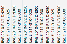
| RVB 2010-F1/R1 | Application range extension set RVB 2010-F1/1 DN250 for DN300 | 211-3102-010 |
| RVB 2010-F1/R2 | Application range extension set RVB 2010-F1/2 DN250 for DN300 | 211-3104-010 |
| RVB 2010-F1/R3 | Application range extension set RVB 2010-F1/3 DN250 for DN300 | 211-3106-010 |
| BYPASS ELEMENTS AND SETS |
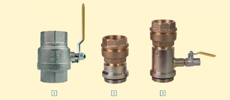
The elements are mounted on the ball valve used for the drilling of the pipeline and it will be connected by the by-pass pipeline PE DN63.

| Sets | |||
| Item No. | Name | Catalogue No. | No. of units |
| Set for bypass | 211-3110-010 | ||
| The set contains: | |||
| 1. | Ball valve FF 2.5” PR65 | 212-2010-004 | 2 |
| 2. | Adapter F-M PE63-2.5” L | 212-3110-042 | 1 |
| 3. | Adapter F-M PE63-2.5” L with pressure relief | 212-3110-095 | 1 |
| Set for bypass - double | 211-3110-020 | ||
| The set contains: | |||
| 1. | Ball valve FF 2.5” PR65 | 212-2010-004 | 4 |
| 2. | Adapter F-M PE63-2.5” L | 212-3110-042 | 2 |
| 3. | Adapter F-M PE63-2.5” L with pressure relief | 212-3110-095 | 2 |
| Individual components | ||
| Item No. | Name | Catalogue No. |
| 1. | Ball valve FF 2.5” PR65 | 212-2010-004 |
| 2. | Adapter F-M PE63-2.5” L | 212-3110-042 |
| 3. | Adapter F-M PE63-2.5” L with pressure relief | 212-3110-095 |
 Czech
Czech