 Czech
Czech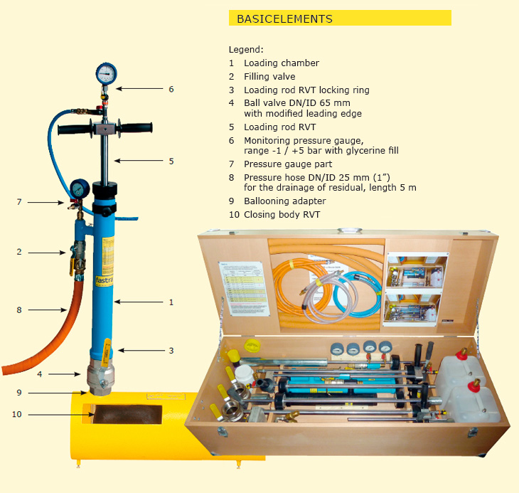
Description and working range RVB 2010-F1
Standard ballooning sets are configured of individual elements of the RVB 2010-F system so that they could make it possible for system and complete execution of works at preserving the maximum possible safety level. In principle, they are designed as at least two-chamber units at every side of the closed section (two loading chambers with closing balloons are used at every side of the closed section). For the list of sets including their working range see the next page. For schematic representations of pipeline closing, method of the loading of the closing bodies, layout of ballooning adapting pieces and pictures of individual set elements see the sheets 2.1-1.2 and 2.1.-2. The sets are normally supplied with basic accessories as specified in the set content description on the sheet 2.1-3.1.
Connecting thread dimension:
G2½” outer to EN 228-1:2003
The total height of the chamber with the ball installed and loading rod fully pulled out (measured form the surface of the pipeline being closed): 1850 mm
The weight of this version for DN3000 including transport boxes:
One sided 139 kg
Two sided 265 kg
Three sided 391 kg
| DIAMATER AND MATERIAL OF CLOSED PIPELINE | ||||
| Closed pipeline diameter | ||||
| Set | Closing type (set) | Steel DN/ID [mm] | PE DN/OD [mm] | Catalogue No. |
| RVB 2010-F1/1 DN 250 | Single-sided, two-chamber | 65 - 250 | 75 - 315 | 211-3102-025 |
| RVB 2010-F1/1 DN 300 | Single-sided, two-chamber | 65 - 300 | 75 - 315 | 211-3102-030 |
| RVB 2010-F1/2 DN 250 | Two-sided, two-chamber | 65 - 250 | 75 - 315 | 211-3104-025 |
| RVB 2010-F1/2 DN 300 | Two-sided, two-chamber | 65 - 300 | 75 - 315 | 211-3104-030 |
| RVB 2010-F1/3 DN 250 | Three-sided, two-chamber | 65 - 250 | 75 - 315 | 211-3106-025 |
| RVB 2010-F1/3 DN 300 | Three-sided, two-chamber | 65 - 300 | 75 - 315 | 211-3106-030 |
For the content of individual sets following the sheet page 2.1-3.1
Range of the application of the sets up to DN250, steel, may be extended up to DN300 using optional
accessories – following the sheet 2.1-3.1
| MEDIA IN CLOSED PIPELINE | ||||
| Natural gas, water, other non-aggressive gases and liquids. Other media may be used based on consultation with the manufacturer. |
| MAXIMUM PRESURE IN THE CLOSED PIPELINE | |||
| Pipeline closed dimension | |||
| Steel DN/ID * [mm] |
PE DN/OD * [mm] |
Maximum permitted pressure in the closed pipeline |
Minimum number of RVT (chambers used) |
| DN65 – DN100 (76,1 – 114,3) |
75 - 110 | 3,0 bar | |
| DN125 – DN150 (133,0 - 168,3) |
126 - 160 | 2,0.bar | |
| DN200 (211,0 – 219,1) |
180 - 225 | 1,5 bar | 2 |
| DN250 (273,0) |
250 - 280 | 1,2 bar | |
| DN300 (318,0 – 323,9) |
315 | 1,0 bar | |
| WORKING TEMPERATURE | ||||
| -10/+80°C |