 Czech
Czech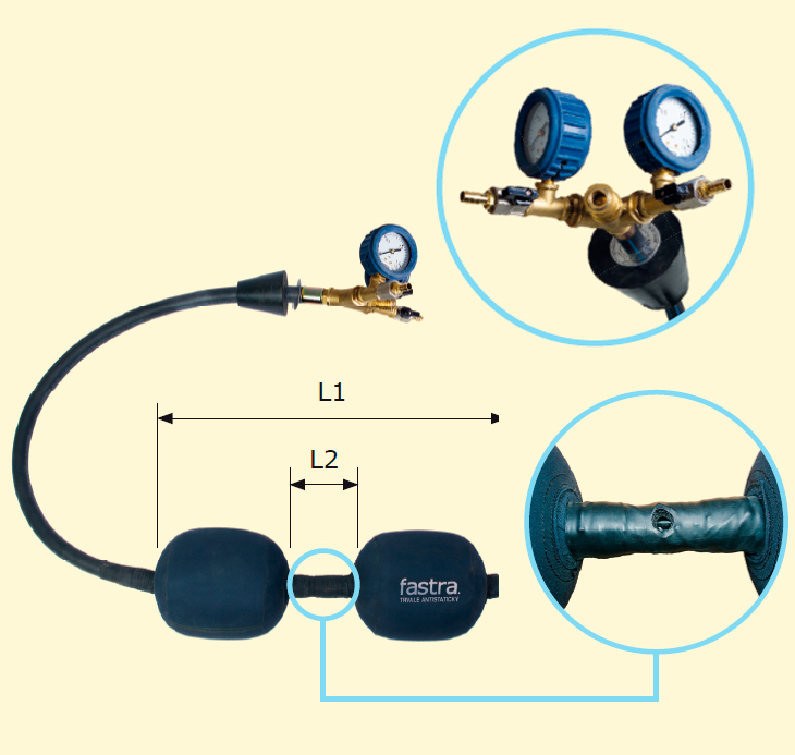
Type UBF-N-2
A version with two independently filled balloons and an opening/passage allowing for the control of the pressure or drainage of the medium (or, as the case may be, other functions like de-aeration, gas drainage, filling with inert gas and the like) from the area as between the two balloons. Working part – for properties and description following the sheet 2.2 –3. Loading part – a flexible loading tube with a sealing plug, an opening/passage in the working part of the rear balloon and the loading tube ended with a self-closing quick acting coupling system, two integrated pressure gauges with a two hose extensions diameter 10 mm, identification plate. This type of the closing balloon in this versions is made of materials that must not be exposed to any organic solvents, oil products, fats, acids, caustics and their vapours. The version made be modified based on customer requirements (following the sheet 2.2-1).
| FOR STEEL PIPELINES | |||||||||
| Name | For pipeline DN/ID [mm] |
L [mm] |
L1 [mm] |
L2 [mm] |
P1 [bar] |
P2 [bar] |
D [mm] |
H | Catalogue No. |
| UBF–N-2 DN80 | 80 | 1000 | 390 | 100 | 0,25 | 2,5 | 57 | FHS | 221-3400-080 |
| UBF–N-2 DN100 | 100 | 1000 | 460 | 100 | 0,22 | 2,2 | 57 | FHS | 221-3400-100 |
| UBF–N-2 DN125 | 125 | 1000 | 540 | 100 | 0,20 | 2,0 | 57 | FHS | 221-3400-125 |
| UBF–N-2 DN150 | 150 | 1000 | 600 | 100 | 0,18 | 1,8 | 74 | FHXX | 221-3400-150 |
| UBF–N-2 DN200 | 200 | 1000 | 680 | 100 | 0,14 | 1,4 | 74 | FHXX | 221-3400-200 |
| UBF–N-2 DN250 | 250 | 1000 | 820 | 100 | 0,12 | 1,2 | 74 | FHXX | 221-3400-250 |
| UBF–N-2 DN300 | 300 | 1000 | 1000 | 100 | 0,10 | 1,0 | 90 | FHXX | 221-3400-300 |
| UBF–N-2 DN350 | 350 | 1000 | 1080 | 100 | 0,06 | 0,6 | 90 | FHXX | 221-3400-350 |
| UBF–N-2 DN400 | 400 | 1000 | 1160 | 100 | 0,05 | 0,5 | 90 | FHXX | 221-3400-400 |
| UBF–N-2 DN450 | 450 | 1000 | 1240 | 100 | 0,04 | 0,4 | 140 | příruba DN150 | 221-3400-450 |
| UBF–N-2 DN500 | 500 | 1000 | 1320 | 100 | 0,04 | 0,4 | 140 | příruba DN150 | 221-3400-500 |
In addition to the above dimensions, balloons may be manufactured with dimensions individually requested by customers.
L - length of the loading tube to the rear balloon (from the rear side of the rear balloon to the fitting set)
L1, L2 - for dimensions following the figure
P1 - maximum medium pressure in the closed pipeline
P2 - maximum balloon filling pressure
D - minimum diameter of the opening for the balloon loading
H - recommended type of FASTRA ballooning neck for the balloon loading
| FOR PE SDR11 PIPELINES | ||||||||
| Name | For pipeline dn/OD [mm] |
L [mm] |
L1 [mm] |
L2 [mm]; |
P1 [bar] |
P2 [bar] |
D [mm] |
Catalogue No. |
| UBF-N-2 PE90/11 | 90 | 1000 | 390 | 100 | 0,25 | 2,5 | 57 | 221-3401-090 |
| UBF-N-2 PE110/11 | 110 | 1000 | 460 | 100 | 0,20 | 2,0 | 57 | 221-3401-110 |
| UBF-N-2 PE160/11 | 160 | 1000 | 600 | 100 | 0,18 | 1,8 | 74 | 221-3401-160 |
| UBF–N-2 PE225/11 | 225 | 1000 | 680 | 100 | 0,14 | 1,4 | 74 | 221-3401-225 |
| UBF–N-2 PE315/11 | 315 | 1000 | 820 | 100 | 0,10 | 1,0 | 74 | 221-3401-315 |
| UBF–N-2 PE355/11 | 355 | 1000 | 1000 | 100 | 0,06 | 0,6 | 90 | 221-3401-355 |
| UBF–N-2 PE400/11 | 400 | 1000 | 1080 | 100 | 0,05 | 0,5 | 90 | 221-3401-400 |
| UBF–N-2 PE450/11 | 450 | 1000 | 1160 | 100 | 0,04 | 0,4 | 90 | 221-3401-450 |
| FOR PE SDR17 PIPELINES | ||||||||
| Name | For pipeline dn/OD [mm] |
L [mm] |
L1 [mm] |
L2 [mm]; |
P1 [bar] |
P2 [bar] |
D [mm] |
Catalogue No. |
| UBF-N-2 PE90/17 | 90 | 1000 | 390 | 100 | 0,25 | 2,5 | 57 | 221-3407-090 |
| UBF-N-2 PE110/17 | 110 | 1000 | 460 | 100 | 0,20 | 2,0 | 57 | 221-3407-110 |
| UBF-N-2 PE160/17 | 160 | 1000 | 600 | 100 | 0,18 | 1,8 | 74 | 221-3407-160 |
| UBF–N-2 PE225/17 | 225 | 1000 | 680 | 100 | 0,14 | 1,4 | 74 | 221-3407-225 |
| UBF–N-2 PE315/17 | 315 | 1000 | 820 | 100 | 0,10 | 1,0 | 74 | 221-3407-315 |
| UBF–N-2 PE355/17 | 355 | 1000 | 1000 | 100 | 0,06 | 0,6 | 90 | 221-3407-355 |
| UBF–N-2 PE400/17 | 400 | 1000 | 1080 | 100 | 0,05 | 0,5 | 90 | 221-3407-400 |
| UBF–N-2 PE450/17 | 450 | 1000 | 1160 | 100 | 0,04 | 0,4 | 90 | 221-3407-450 |
In addition to the above dimensions, balloons may be manufactured with dimensions individually requested by customers.
SDR - standard dimension ratio – dn/en (the rated external diameter in mm/ rated thickness of the wall in mm)
L - length of the loading tube to the rear balloon (from the rear side of the rear balloon to the fitting set)
L1, L2 - for dimensions following the figure
P1 - maximum medium pressure in the closed pipeline
P2 - maximum balloon filling pressure
D - minimum diameter of the opening for the balloon loading